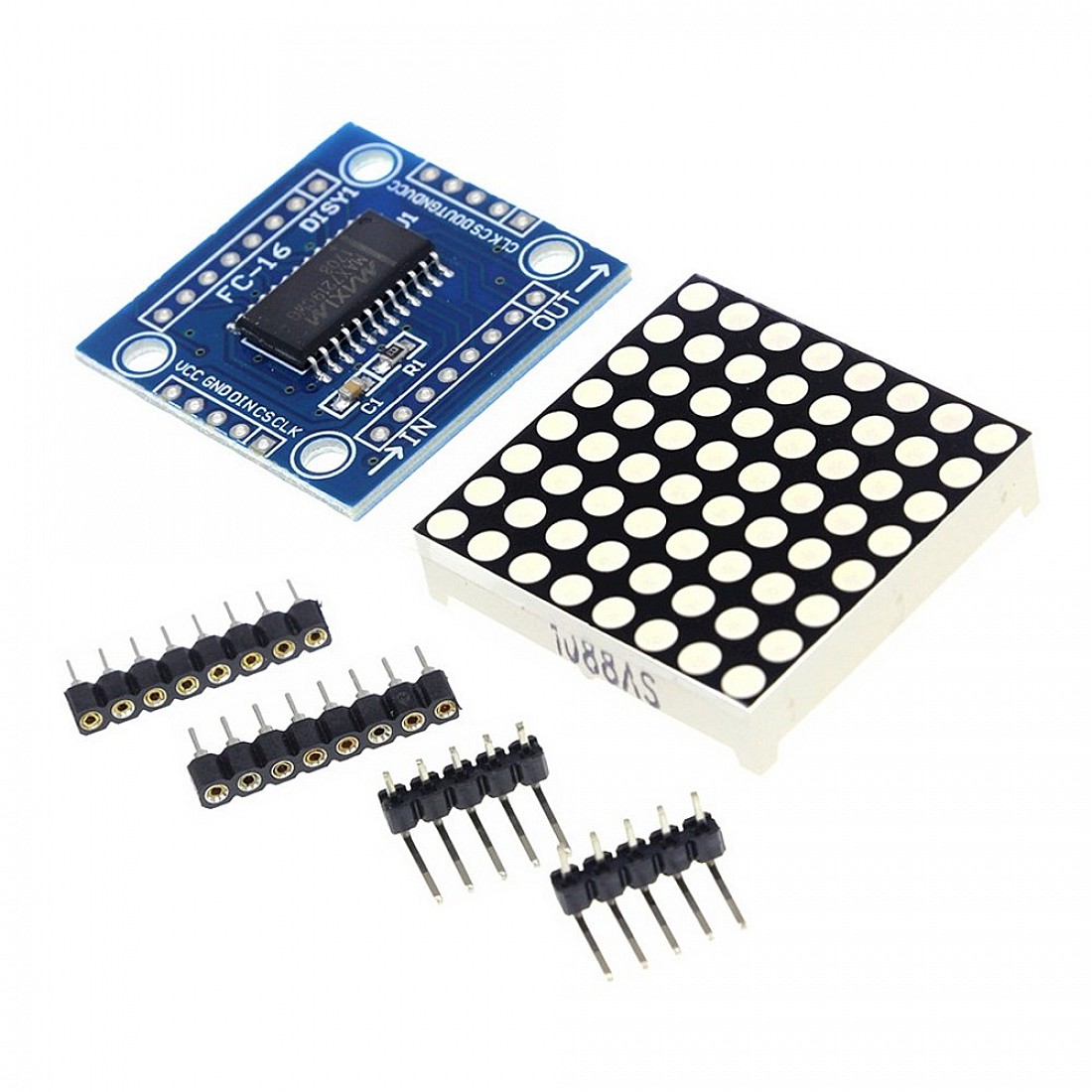

I am worried now, because I also bought some 8x8 LED matrices from your seller. I hope that makes sense.īasically, with these DIY kits, your seller needs to send you the row cathode column anode 8x8 LED matrix and the MAX7219 connected to the correct pins on the 8x8. I bought ten these row anode column cathode 8x8 but not with the PCB. If you DIY kits came with the 1088BS, you won't be able to use the 1088BS without a lot of re-wiring. So, they are the right type, but the MAX7219 are wired to different pins. The DIY kits that I bought on eBay came with the 1088AS. This is how I soldered both of them, with 1088AS is working fine, but not for 1088BS. So ieee488, should I invert the side of soldering for the led module? at the opposite side of the max72xx chip ? From this seller they are labelled 1088BS ( from schematics, it stand for common anode ) and the ones from the other seller are labelled 1088AS ( stand for common cathode ). It's the specification of the led modules. What I could understand so far: as I bought some of theses kits from another seller and they are working fine. I got a few of them from same ebay seller as digger955 and got same issue. What am I doing wrong? Can someone help me? A library meant for people who have little/no knowledge about Arduino to drive an LED matrix display with text with a focus on performance and simplicity. leave the MAX72XX from power-saving mode A library for the MAX7219 LED display drivers.

Lc.setLed(0,col,row,false) // turns off LED at col, rowįrom this site and uploaded it to the Arduino, but I only get some wierd animations (I've uploaded a video here).Īfter that I wrote a new program which only purpose is to show a blank screen, but even that doesn't work, there are still four LEDs turned on //we have to include the library Lc.setLed(0,col,row,true) // turns on LED at col, row Lc.setIntensity(0,8) // sets brightness (0~15 possible values) State of the 8x8 matrix can be presented as an unsigned long integer (uint64t). Samples below implement this animation: These samples use a LedControl (library for the MAX7221 and MAX7219 Led display drivers) to switch LEDs ON/OFF. Lc.shutdown(0,false) // turn off power saving, enables display LED Dot matrix driven by MAX7219 works perfect with Arduino. the zero refers to the MAX7219 number, it is zero for 1 chip pin 12 is connected to the MAX7219 pin 1

#Arduino led matrix max7219 code#
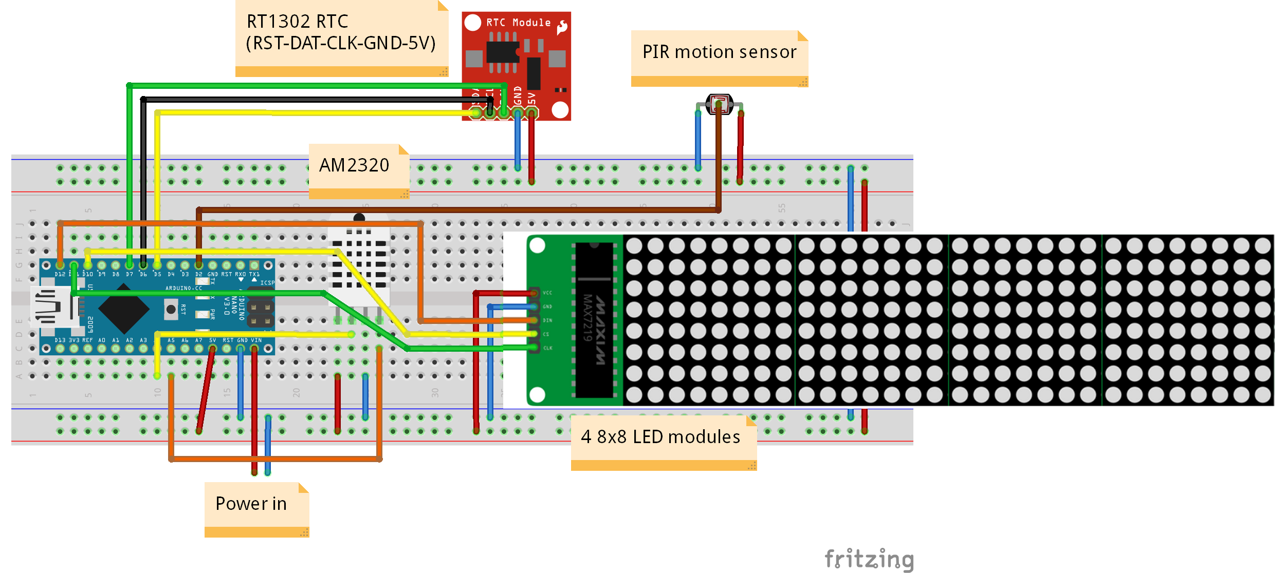
I copied the follwing code #include "LedControl.h" // need the library Place the four matrices next to each other so that there is no space left between them (see picture) Now you have to connect all the VCC PINs of all the four matrices.I've just bought an 8x8 LED matrix with a MAX7219 ( Link) an hooked it up to my Arduino UNO R3, but somehow the LED matrix doesn't do what it should supposed to do. and the output header PINs should show up at the top). Plug them through the input headers (the MAX7219 chip should be below the LED matrix). Let's wire the LED matrices: First use the breadboard to plug the matrices.

Normally, the voltage supply of +5V is used. Its operation is specified in a voltage range of +4.0 to +5.5V.
#Arduino led matrix max7219 serial#
Some key features of MAX7219 include: It is an LED driver display IC with a 10MHz serial interface which allows the user to select the decode/No-Decode digit. For the rest of the PINs (VCC, GND, CS and CLK), the PIN at the input header is physically connected/shortcut to the PIN at the output header (this is because all the MAX7219 are daisy-chained sharing an SPI bus). It is one of the most popular displays driver IC. The difference between input and ouput only applies to the data PIN (DIN and DOUT). The LED Matrix modules have two sets of male header PINs, one for input (the PINs located closer to the MAX 7219 chip) and one for output.


 0 kommentar(er)
